Modeling Scheme Design
Modeling Scheme Design
This section introduces how to transform time series data application scenarios into IoTDB time series mode.
1. Time Series Data Mode
Before designing an IoTDB data mode, it's essential to understand time series data and its underlying structure. For more details, refer to: Basic Concepts
2. Tree-Table Twin Mode in IoTDB
IoTDB offers tree-table twin mode, each with its distinct characteristics as follows:
Tree Mode: It manages data points as objects, with each data point corresponding to a time series. The data point names, segmented by dots, form a tree-like directory structure that corresponds one-to-one with the physical world, making the read and write operations on data points straightforward and intuitive.
- When performing data mode, to meet sufficient performance requirements, it is recommended that the penultimate layer node (corresponding to the number of devices) in the data path (Path) contains no fewer than 1,000 entries. The number of devices is linked to concurrent processing capability—a higher number of devices ensures more efficient concurrent read and write operations.
In scenarios where "the number of devices is small but each device contains a large number of data points" (e.g., only 3 devices, each with 10,000 data points), it is advisable to add a .value level at the end of the path. This increases the total number of nodes in the penultimate layer. Example: root.db.device01.metric.value.- When constructing tree mode paths, if node naming may include non-standard characters or special symbols, it is recommended to implement a backtick encapsulation strategy for all hierarchical nodes. This approach effectively mitigates issues such as probe registration failures and data write interruptions caused by character parsing errors, ensuring the accuracy of path identifiers in syntax parsing.
Table Mode: It is recommended to create a table for each type of device. The collection of physical quantities from devices of the same type shares certain commonalities (such as the collection of temperature and humidity physical quantities), allowing for flexible and rich data analysis.
2.1 Mode Characteristics
Tree-table twin mode syntaxes have their own applicable scenarios.
The following table compares the tree mode and the table mode from various dimensions, including applicable scenarios and typical operations. Users can choose the appropriate mode based on their specific usage requirements to achieve efficient data storage and management.
| Dimension | Tree Mode | Table Mode |
| Applicable Scenarios | Measurements management, monitoring scenarios | Device management, analysis scenarios |
| Typical Operations | Read and write operations by specifying data point paths | Data filtering and analysis through tags |
| Structural Characteristics | Flexible addition and deletion, similar to a file system | Template-based management, facilitating data governance |
| Syntax Characteristics | Concise and flexible | Rich analysis |
| Performance Comparison | Similar | |
Notes:
- Both mode spaces can coexist within the same cluster instance. Each mode follows distinct syntax and database naming conventions, and they remain isolated by default.
2.2 Model Selection
IoTDB supports model selection through various client tools. The configuration methods for different clients are as follows:
When connecting via CLI, specify the model using the sql_dialect parameter (default: tree model).
# Tree model
start-cli.sh(bat)
start-cli.sh(bat) -sql_dialect tree

# Table model
start-cli.sh(bat) -sql_dialect tableUse the SET statement to switch models in SQL:
-- Tree model
IoTDB> SET SQL_DIALECT=TREE

-- Table model
IoTDB> SET SQL_DIALECT=TABLE- Application Programming Interfaces (APIs)
For multi-language APIs, create connections via model-specific session/session pool classes. Examples:
// Tree model
SessionPool sessionPool =
                new SessionPool.Builder()
                        .nodeUrls(nodeUrls)
                        .user(username)
                        .password(password)
                        .maxSize(3)
                        .build();

// Table model
ITableSessionPool tableSessionPool =
                new TableSessionPoolBuilder()
                        .nodeUrls(nodeUrls)
                        .user(username)
                        .password(password)
                        .maxSize(1)
.build();# Tree model
session = Session(
ip=ip,
port=port,
user=username,
password=password,
fetch_size=1024,
zone_id="UTC+8",
enable_redirection=True
)
# Table model
config = TableSessionPoolConfig(
node_urls=node_urls,
username=username,
password=password,
database=database,
max_pool_size=max_pool_size,
fetch_size=fetch_size,
wait_timeout_in_ms=wait_timeout_in_ms,
)
session_pool = TableSessionPool(config)// Tree model
session = new Session(hostip, port, username, password);
// Table model
session = (new TableSessionBuilder())
->host(ip)
->rpcPort(port)
->username(username)
->password(password)
->build();// Tree model
config := &client.PoolConfig{
Host: host,
Port: port,
UserName: user,
Password: password,
}
sessionPool = client.NewSessionPool(config, 3, 60000, 60000, false)
defer sessionPool.Close()
// Table model
config := &client.PoolConfig{
Host: host,
Port: port,
UserName: user,
Password: password,
Database: dbname,
}
sessionPool := client.NewTableSessionPool(config, 3, 60000, 4000, false)
defer sessionPool.Close()// Tree model
var session_pool = new SessionPool(host, port, pool_size);
// Table model
var tableSessionPool = new TableSessionPool.Builder()
.SetNodeUrls(nodeUrls)
.SetUsername(username)
.SetPassword(password)
.SetFetchSize(1024)
.Build();For the table model, include sql_dialect=table in the JDBC URL:
// Tree model
Class.forName("org.apache.iotdb.jdbc.IoTDBDriver");
Connection connection = DriverManager.getConnection(
                "jdbc:iotdb://127.0.0.1:6667/", username, password);

// Table model
Class.forName("org.apache.iotdb.jdbc.IoTDBDriver");
Connection connection = DriverManager.getConnection(
                "jdbc:iotdb://127.0.0.1:6667?sql_dialect=table", username, password);
2.3 Tree-to-Table Conversion
IoTDB supports tree-to-table conversion, as shown in the figure below:
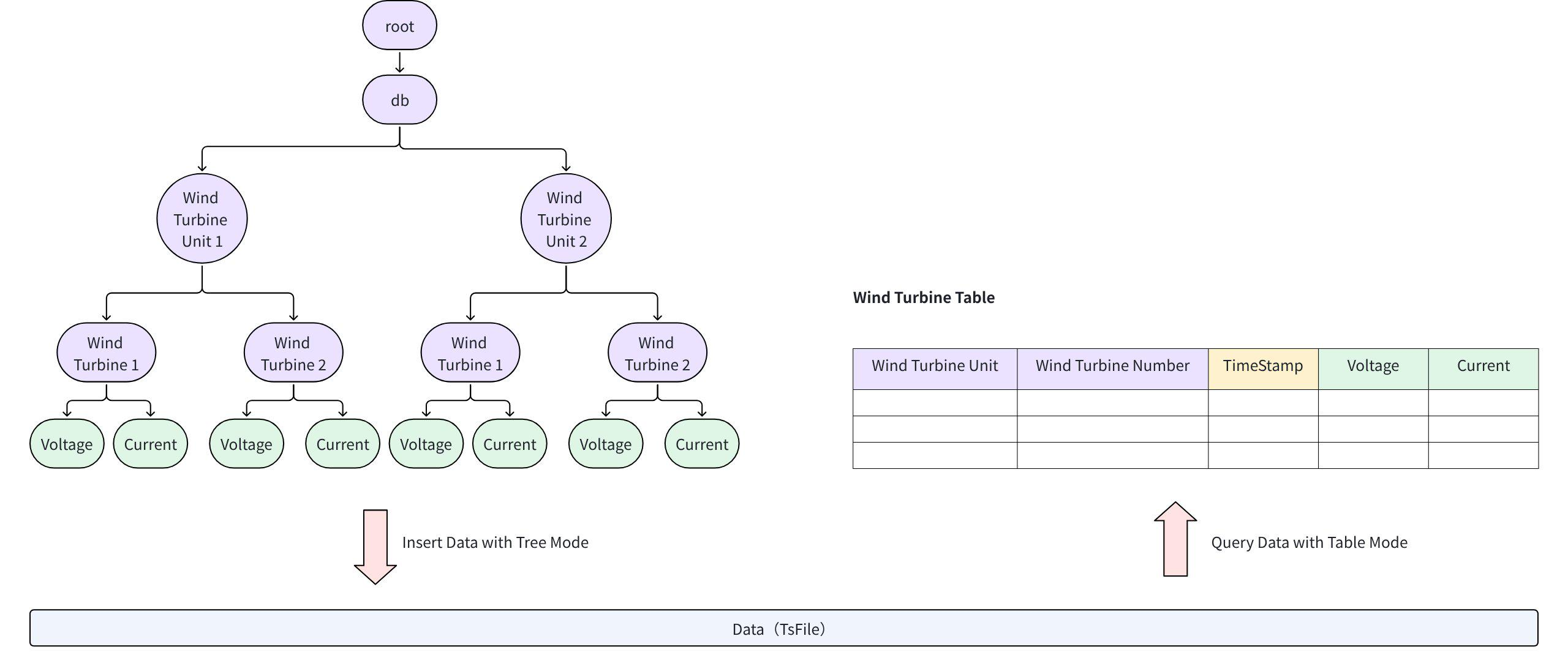
This feature allows existing tree-model data to be transformed into table views. Users can then query the same dataset using either model. Detailed instructions are available in Tree-to-Table View. Note: SQL statements for creating tree-to-table views must be executed in table mode.
3. Application Scenarios
The application scenarios mainly include two categories:
Scenario 1: Using the tree mode for data reading and writing.
Scenario 2: Using the table mode for data reading and writing.
3.1 Scenario 1: Tree Mode
3.1.1 Characteristics
Simple and intuitive, corresponding one-to-one with monitoring points in the physical world.
Flexible like a file system, allowing the design of any branch structure.
Suitable for industrial monitoring scenarios such as DCS and SCADA.
3.1.2 Basic Concepts
| Concept | Definition |
|---|---|
| Database | Definition: A path prefixed with root..Naming Recommendation: Only include the next level node under root, such as root.db.Quantity Recommendation: The upper limit is related to memory. A single database can fully utilize machine resources; there is no need to create multiple databases for performance reasons. Creation Method: Recommended to create manually, but can also be created automatically when a time series is created (defaults to the next level node under root). |
| Time Series (Data Point) | Definition: A path prefixed with the database path, segmented by ., and can contain any number of levels, such as root.db.turbine.device1.metric1.Each time series can have different data types. Naming Recommendation: Only include unique identifiers (similar to a composite primary key) in the path, generally not exceeding 10 levels. Typically, place tags with low cardinality (fewer distinct values) at the front to facilitate system compression of common prefixes. Quantity Recommendation: The total number of time series manageable by the cluster is related to total memory; refer to the resource recommendation section. There is no limit to the number of child nodes at any level. Creation Method: Can be created manually or automatically during data writing. |
| Device | Definition: The second-to-last level is the device, such as device1 in root.db.turbine.device1.metric1.Creation Method: Cannot create a device alone; it exists as time series are created. |
3.1.3 Mode Examples
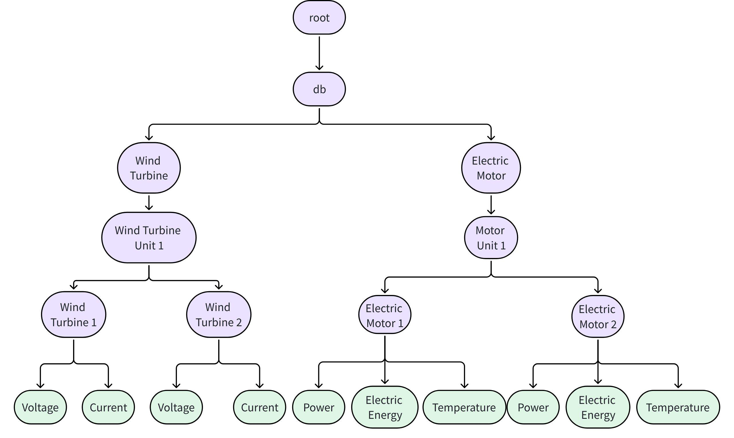
3.1.3.1 How to mode when managing multiple types of devices?
- If different types of devices in the scenario have different hierarchical paths and data point sets, create branches under the database node by device type. Each device type can have a different data point structure.
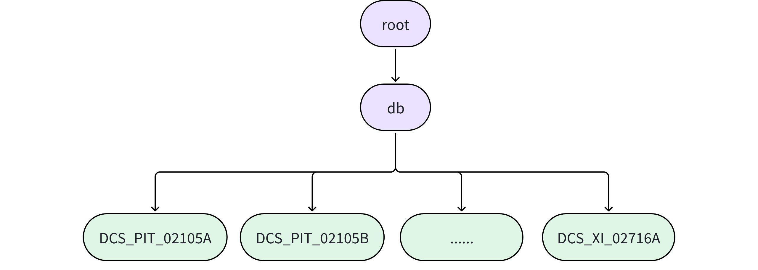
3.1.3.2 How to when there are no devices, only data points?
- For example, in a monitoring system for a station, each data point has a unique number but does not correspond to any specific device.
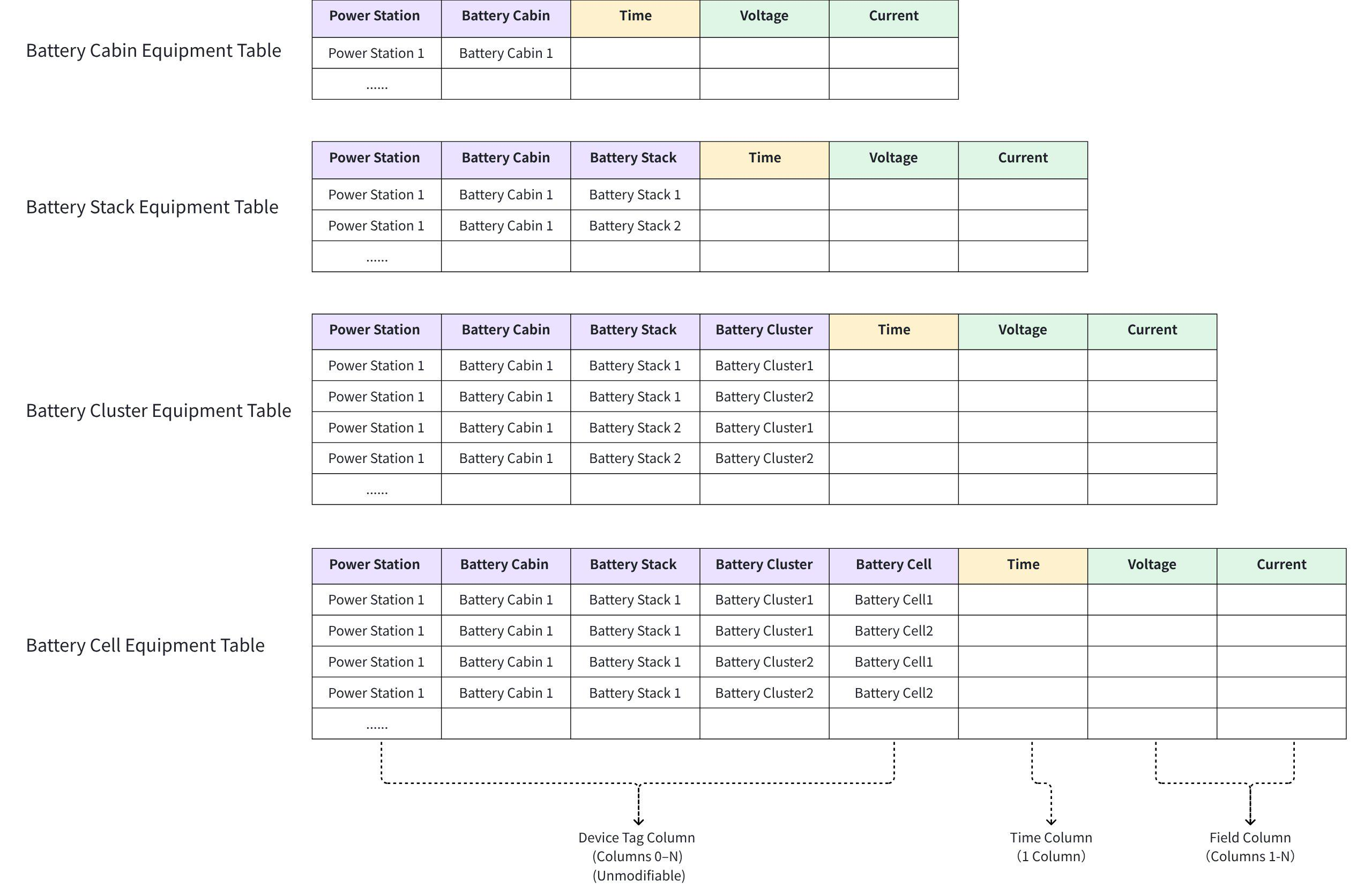
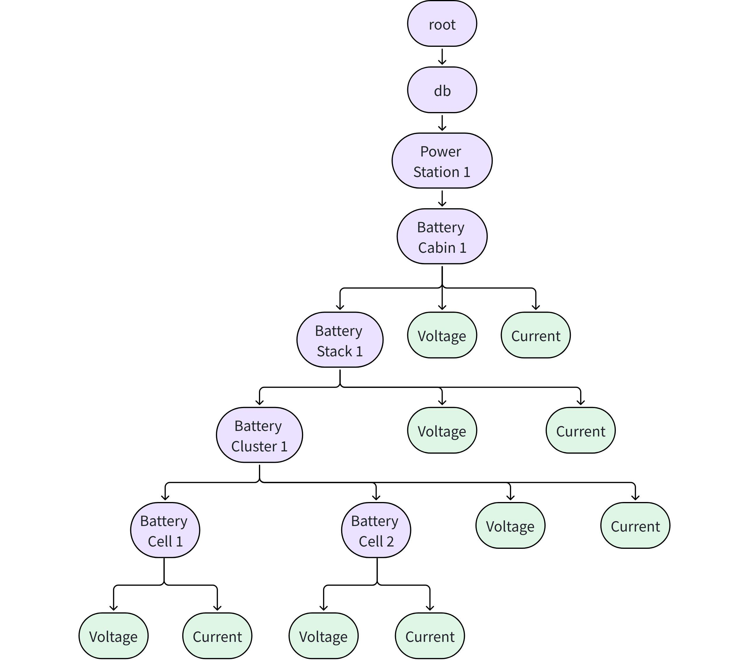
3.1.3.3 How to mode when a device has both sub-devices and data points?
- For example, in an energy storage scenario, each layer of the structure monitors its voltage and current. The following mode approach can be used.
3.2 Scenario 2: Table Mode
3.2.1 Characteristics
Modes and manages device time series data using time series tables, facilitating analysis with standard SQL.
Suitable for device data analysis or migrating data from other databases to IoTDB.
3.2.2 Basic Concepts
Database: Can manage multiple types of devices.
Time Series Table: Corresponds to a type of device.
| Category | Definition |
|---|---|
| Time Column (TIME) | Each time series table must have a time column named time, with the data type TIMESTAMP. |
| Tag Column (TAG) | | Unique identifiers (composite primary key) for devices, ranging from 0 to multiple. Tag information cannot be modified or deleted but can be added. Recommended to arrange from coarse to fine granularity. |
| Data Point Column (FIELD) | | A device can collect 1 to multiple data points, with values changing over time. There is no limit to the number of data point columns; it can reach hundreds of thousands. |
| Attribute Column (ATTRIBUTE) | Supplementary descriptions of devices, not changing over time. Device attribute information can range from 0 to multiple and can be updated or added. A small number of static attributes that may need modification can be stored here. |
Data Filtering Efficiency: Time Column = Tag Column > Attribute Column > Data Point Column.
3.2.3 Mode Examples
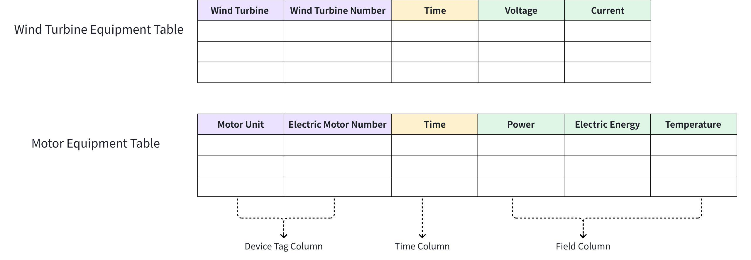
3.2.3.1 How to mode when managing multiple types of devices?
Recommended to create a table for each type of device, with each table having different tags and data point sets.
Even if devices are related or have hierarchical relationships, it is recommended to create a table for each type of device.
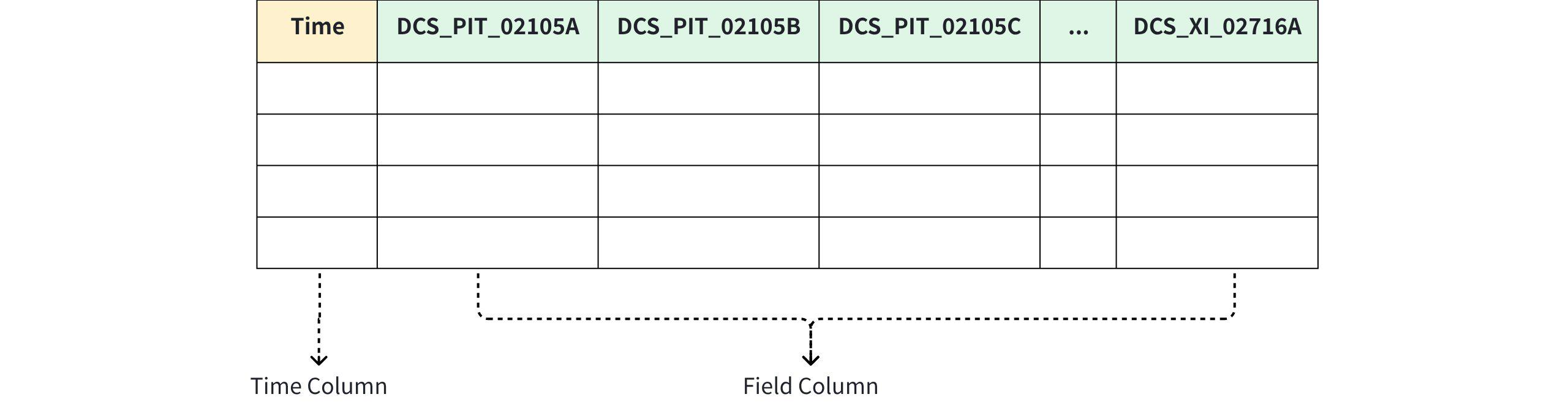
3.2.3.2 How to mode when there are no device identifier columns or attribute columns?
- There is no limit to the number of columns; it can reach hundreds of thousands.
3.2.3.3 How to mode when a device has both sub-devices and data points?
- Each device has multiple sub-devices and data point information. It is recommended to create a table for each type of device for management.